The edge connector on the micro:bit board brings out all the key signals and circuits that you would need in order to build attachments to the micro:bit. 5 of the pads are large rings with 4mm through plated holes suitable for attaching standard banana plugs, or for clipping crocodile clips to. 3 of these are connected to GPIO pins that are also capable of analog, PWM and touch sensing. The 3V and GND rings are useful for providing a small amount of power to external circuits, or (carefully) back powering the micro:bit from an external power supply.
The smaller strips spaced at 1.27mm on the edge connector have additional signals, some of which are used by the micro:bit, and others that are free for you to use.
Connector Pin Layout
Since some of the pins are internally connected, it is recommended not to use them for external connections. The input/output ports can be set internally to different modes, but the explicit mode change by a Python function is not supported by the MicroPython firmware. To make it simple the mode is automatically selected by the function call of the pinN objects (N = 0..20) (with the exception of display.off() that turns off display mode).
Pins for general digital-in/digital-out:
Function
Pins
N
Method call
Capabilities
Digital in
0, 1, 2, 8, 12, 16
pinN.read_digital()
Pulldown 10 kOhm
Digital in
0, 1, 2, 8, 12, 16
pinN.isTouched
Pullup 10 kOhm
Digital out Hi
0, 1, 2, 8, 12, 16
pinN.write_digital(1)
Max drive current 5 mA
Digital out Lo
0, 1, 2, 8, 12, 16
pinN.write_digital(0)
Max sink current 5 mA
Pins for analog-in:
Function
Pins
N
Method call
Capabilities
Analog in
0, 1, 2
pinN.read_analog()
Input impedance 10 MOhm
Maximum voltage range when pin is used as input: -0.3V .. 3.9V (avoid overshoot with inductive loads as speakers, motors, piezo sounder)
Pins for PWM
Function
Pins
N
Method call
Puls-width modulation (PWM)
0, 1, 2
pinN.write_analog(duty)
pinN.set_analog_period(period)
duty = 0.0 ... 1023.0 (100%)
period in Milliseconds
Pins not available for general GPIO use:
Display mode P3, P4, P6, P7, P9, P10
After calling display.off(), these pins can be used for general input/output, but for some unknown reason the interpreter prompt is unavailable after an exception is raised (firmware flash necessary). Workaround: Execute error-prone code in a try-except block.
try:
error-prone code, e.g. pin3.read_digital()
except Exception as e:
print("Exception raised: " + str(e))
Button mode P5, P11, pullup 10 k, buttons connects to GND
may be uses externally
SPI mode P13, P14, P15
may be used externally
I2C mode P19, P20, pullup 10 k
may be used externally, but accelerometer stops to work
Connecting speakers, motors, buzzers, relays and simular
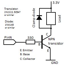
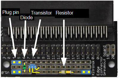
Due to the small driving capacity in digital or analog output mode, it is highly recommended to use a simple transistor amplifier that is easy built on an edge connector (e.g. from Kitronik, Code: 5601B). A clamp diode also eliminates harm from inductive feedback voltage of solenoid-like devices. Plug pins may be soldered to make connection easy and adaptable using jumper cables.
Schematics
Wiring
Remarks:
The cathode of the diode has a black label and is connected to the + strip. A resistor has no polarity. Check the data sheet of your transistor to find the wires C, B and E.
Example: Connection a small speaker
PHOTO TODO
Example 1: Blinking LED, Beeping Buzzer
Aim:
Make a LED blinking or a buzzer beeping with a 1 second period. When button B is pressed, the program should halt.
Wiring:
Connect a LED to pin0 and GND in series with an resistor with 470 Ohm to 1 kOhm. Respect the polarity of the LED (long wire on flat side is connected to pin0).
Remarks: img = Image() represents an image with all LEDs turned off. img.invert() returns an image, where all LEDs are inverted, so turned on.
Example 2: Detect broken wire
Aim:
The micro:bit acts as alarm system: Place a a thin wire place in front of a treasure to protect. If the wire is in place, the center LED blinks (indicating that the system is armed). If the wire is broken, all LEDs of the dot matrix display are blinking (if a buzzer or speaker is available, an alarm signal is emitted).
Wiring:
Connect the wire to pin0 and VCC. A digital High is detected. When the connection is broken, pin0 is pulled-down to digital Low due to the internal pulldown resistor. You can test the system by using a short wire with crocodile clips or banana plugs between pin0 and VCC.
 LinkUp
 TCPCom
 Simulations